How 2026 F1 sidepod cooling inlet regulations impact aerodynamics
The 2026 power unit shift to a 50/50 power split increases thermal loads from the 350kW MGU-K. This forces teams to redesign sidepod inlets and undercuts to manage mass flow spillage and maintain diffuser pressure.

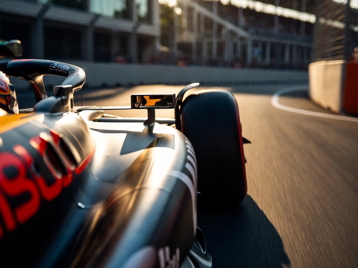
The thermal shift in power unit requirements
The 2026 power unit changes the thermal management priorities for every team on the grid. The new 1.6-litre V6 turbo engine operates with a 50/50 power split between the internal combustion engine and the electrical component. While the internal combustion engine requires less cooling than previous versions, the upscaled hybrid system rejects more heat. The MGU-K delivers approximately 350kW of electrical power, which is a significant increase from the 120kW used in previous regulations. This higher electrical output means teams must manage much larger heat loads from the hybrid components.
Teams typically house the internal combustion engine cooling within the sidepods. They use the roll hoop to feed the lower temperature hybrid and auxiliary systems through central ducts. Because the new combustion engine requires less cooling, the balance of cooling needs shifts toward these hybrid systems. Teams may move more Low Temperature Radiators into the sidepods or increase the size of the air ducts along the centerline. Red Bull exploited a solution in 2025 where they used an additional inlet on top of the sidepod to take advantage of the high pressure area over the sidepod created by the cockpit.
The change in thermal requirements forces a redesign of how air enters the car. If a team optimizes cooling for 35°C but the ambient temperature drops to 10°C, the engine runs too cold and the brakes lose effectiveness. A car running with too much cooling loses straight-line speed because of increased aerodynamic drag. The optimal configuration is the minimum amount of cooling necessary to keep all systems within their operating windows.
Evolution of inlet geometry
The position and shape of the cooling inlet determine how teams manage airflow between the front and rear of the car. After McLaren used slim "r" shaped inlets, several other teams moved toward a squarer inlet design. Every team uses a different philosophy regarding how the inlet interacts with the undercut and the floor. The sidepod bulk shape manages the airflow that travels from the front to the rear of the car.
The design of the sidepod inlets and their relationship to the undercut creates a significant aerodynamic challenge. The sidepod bulk shape determines how much pressure exists over the rear of the car to aid the diffuser. Teams use the sidepod to create high pressure that pushes the tyre wake away from the car. A large undercut allows teams to direct airflow toward the wakeboard and the floor edge. Most teams use an oversized sidepod to create high and flat flanks that push the tyre wake away. The airflow over the top of the sidepod then increases pressure over the diffuser to create downforce.
One team’s design may fail to provide enough outwash to protect the floor. If the front of the sidepod does not generate enough outwash, the vortices that seal the floor will be weak. This weakness allows the front tyre wake to encroach on the floor edge. The teams must decide if they want to prioritize a slim inlet for low drag or a larger inlet for better airflow management.
The undercut and mass flow spillage
The Mercedes design lacks an undercut area, which creates a specific aerodynamic problem. The radiator inlet sits in the middle of the flow area rather than being detached from the leading edge of the underfloor. As the car reaches high speeds, the radiator cannot process the entire mass flow. This creates a blockage that forces the excess flow to spill around the leading edge of the inlet. The low pressure under the car pulls this spilled mass flow toward the underfloor. This spillage can cause the central part of the underfloor to stall, which produces porpoising.
The Red Bull concept uses a wide undercut to manage this mass flow. This design directs the airflow around the rear tyre and helps the floor edge. The Red Bull sidepod uses a protruding upper edge and specific vertical and horizontal cooling slots to manage airflow, which helps direct the wake around the rear tyre and away from the diffuser to maintain consistency. This separation of the inlet from the floor edge helps prevent the radiator spillage from affecting the underfloor pressure.
The height and width of the floor leading edge control how much mass flow enters the underfloor. Some mass flow turns outwards to create vortices that seal the floor, while other mass flow travels under the central area of the floor to feed the diffuser. Will teams find a way to manage radiator spillage without compromising the stability of the underfloor?
New regulatory volumes for cooling ducts
The FIA provides a specific regulatory volume where a duct can sit to feed coolers or the turbo airbox. This volume is located inside the engine cover and resembles the designs used by Benetton in the late 1980s. This allows teams to use the high pressure area over the sidepod to feed the turbo or auxiliary systems. The ability to use these ducts gives teams more flexibility in how they position the sidepod inlets.
The sidepod design also influences how air reaches the diffuser. The airflow over the diffuser depends on the sidepod, the rear suspension, and the floor corner. The floor corner sits just ahead of the rear tyre. The FIA allows slots in the floor corner to drive airflow toward the outer vortex of the diffuser. This design resembles the "mouse hole" seen in 2022. The slots inject energy into the airflow to help it meet the outer vortex at the diffuser wall.
The design of the floor edges and the sidepod must work together to maintain the pressure inside the diffuser. If the sidepod does not direct the air correctly, the floor edge vortices will lose energy. This loss of energy reduces the pressure inside the diffuser and decreases downforce.
The wakeboard and lateral support loophole
The wakeboard directs the turbulent front tyre wake inboard to reduce the car’s wake for the following competitor. The FIA rules favor an inwash design through a triple vane setup. Teams can create a vertical outwash vane shape, but the compromises in the shape likely negate any advantage. The wakeboard must be nearly full size and cannot have transparent openings. Teams can create horizontal openings to create upwash, which aids the floor and creates outwash to push the front tyre wake away from the car.
The wakeboard sits in a highly unsteady airflow, so the FIA allows a lateral beam to support it. This support beam can sit at any height ahead of the sidepod or the floor. Because the support’s shape is small and heavily regulated, its influence on the airflow is a major area of development. A low mounted support influences the airflow ahead of the floor’s leading edge. This allows teams to use the support to manipulate the flow before it reaches the floor.
The design of the wakeboard and its three sections determines the battleground for aerodynamicists. Teams will develop different ideas for the wakeboard throughout the season. The interaction between the wakeboard and the sidepod front remains a primary focus for aerodynamicists.
Sidepod bulk and rear tyre flow
The sidepod bulk shape manages the airflow that travels between the front and the rear of the car. Oversized sidepods create high pressure that pushes the tyre wake away from the car. The airflow over the top of the sidepod increases the pressure over the diffuser. This pressure helps the diffuser work more effectively.
The sidepod also influences the airflow around the rear tyre. The design uses the undercut to direct airflow around the rear tyre. This flow connects with the flow displaced by the rear tyre and the lower tyre squirt. This connection helps maintain flow consistency and reduces the drag generated by the large rear tyres. If the sidepod is too small, the car lacks the pressure needed to push the tyre wake away. This can lead to unpredictable handling in the corners.
The rear suspension also affects the airflow over the diffuser. Although the profile of the wishbones and rods is constrained, teams use their shape and layout to influence the local airflow. The rear suspension components must work alongside the sidepod and the floor to ensure the diffuser receives steady airflow.
Tyre temperature and the FIA hub ban
The FIA prohibits devices that target the cooling of the "Complete Wheels". McLaren previously used a design where air moved through the wheel hub to manage tyre temperatures. This design allowed the team to control the temperature of the tyres by directing air through the hub. The FIA inspected the McLaren cars and found the design was legal, but they later changed the regulations to close this loophole.
The new regulations prevent teams from using the wheel hub to control temperature. This decision follows speculation that teams might use water to cool tyres. The FIA maintains that devices targeting the cooling of the complete wheels are prohibited. This rule change affects how teams manage tyre degradation and grip.
You should observe how the sidepod inlets and brake ducts change between sessions. Larger inlets suggest a team expects hot conditions or prioritizes cooling. Smaller inlets suggest the team wants to reduce drag. The thermal management of the tyres is tied to the cooling of the brakes and the sidepod. If the sidepod does not manage the airflow correctly, it can impact the temperature of the tyres.
2026 Technical Specification Data
The following table provides the technical limits and specifications for the 2026 Formula 1 cars and power units.
| Specification Category | Technical Detail |
|---|---|
| Minimum Car Weight | 768 kg |
| Maximum Wheelbase | 3400 mm |
| Maximum Car Width | 1900 mm |
| Power Split (ICE/Electric) | 50% / 50% |
| MGU-K Power Output | 350 kW |
| Energy Recovery (Braking) | 8.5 MJ per lap |
| Front Tyre Width Reduction | 25 mm |
| Rear Tyre Width Reduction | 30 mm |
| Front Brake Disc Diameter | 325 mm to 345 mm |
| Rear Brake Disc Diameter | 260 mm to 280 mm |
| Brake Disc Thickness | 34 mm |
The 2026 cars are 30kg lighter than the 2022 models. The maximum wheelbase is 3400mm, which is 200mm shorter than previous generations. The width is 1900mm, a reduction of 100mm. The 1.6-litre V6 turbo engine works with an electrical component that provides 350kW of power. The amount of energy that can be recovered during braking is 8.5 MJ per lap. The front tyres are 25mm narrower, and the rears are 30mm narrower than the previous generation.