Investigating FIA steering mechanical data for driver input analysis
Mechanical steering components like rack and pinion mechanisms and Ackerman geometry dictate how driver inputs translate to vehicle movement. Understanding these variables is essential for analyzing driver input and technical regulations like the 2026 FIA standards.

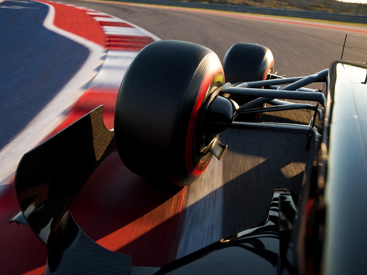
The FIA manages the technical regulations for Formula One through the World Motor Sport Council. This council meets at least three times a year to decide on rules and safety improvements. The FIA also sanctions many other championships like Formula E and the World Rally Championship. In 2026, the cost cap for a Formula One team is US$215 million. Mohammed Ben Sulayem is the president of the FIA. The FIA provides the highest class of racing licenses, known as Super Licences, to drivers. These regulations ensure that all participant cars follow a specific set of rules to maintain competition.
Analyzing the rack and pinion mechanism
The rack and pinion mechanism converts the circular motion of the steering wheel into linear motion. The steering wheel turns the steering shaft, which rotates the pinion gear. The teeth of this pinion gear interlock with a straight row of teeth on the rack. This movement pushes the rack from side to side. The ends of the rack connect to the road wheels through track rods. This system is simple because it contains few moving parts that can wear or displace. BMW was among the first manufacturers to use rack and pinion steering in the 1930s. US manufacturers began using this system with the 1974 Ford Pinto. The diameter of the steering wheel is 15 inches, and when the driver turns the wheel four times from lock to lock, the rim travels nearly 16 feet while the road wheel moves only about 12 inches. This mechanism provides a direct steering feel. The driver feels the road better and has precise control over the movement of the car.
Mechanical advantage in recirculating ball systems
Older designs use the worm and sector or the screw and nut principle. The screw and nut mechanism uses a recirculating ball system to reduce friction. This system places large ball bearings between the screw and the nut. The balls exit from between these two pieces into a channel that connects them. The steering column turns a large screw, which meshes with the nut by using these recirculating balls. This design provides a greater mechanical advantage for larger, heavier vehicles. However, the recirculating ball design has a perceptible lash or dead spot on center where a minute turn of the steering wheel does not move the steering apparatus. This dead spot is adjustable via a screw on the end of the steering box. The worm and sector design was used in older vehicles like the 1960s Ford Falcon. The worm moves a drop arm, which is linked by a track rod to a steering arm that moves the nearest front wheel.
| Steering Component | Function |
|---|---|
| Pinion Gear | Converts rotary motion to linear motion |
| Steering Rack | Moves side to side to steer wheels |
| Tie Rods | Connect steering arms to the drag link |
| Steering Knuckle | Acts as a pivot point for the tires |
| Universal Joint | Connects the column to the rack |
Geometric constraints and Ackerman steering patterns
Effective control requires following Ackerman steering geometry. This geometry accounts for the fact that the inner wheel travels in a path with a smaller radius than the outer wheel. Because of this, the degree of turn for the inner wheel must be greater than the outer wheel. This ensures that the perpendiculars of all four wheels meet at a point called the instantaneous center. When this alignment is correct, all wheels roll without scuffing on the tires. The steering arms are not parallel but are inclined to create the Ackerman Angle. This angle is formed by the lines produced from the inclined arms meeting at the center of the rear axle line. You already know the basics of steering geometry, so I will focus on the specific mechanical variables used in data analysis. The stub axles are turned by steering arms that connect to the tie rod. The tie rods connect the steering arms of both wheels to the drag link.
Evaluating camber angles and tire contact variables
Camber is the angle between the centerline of the tire and the vertical line. You can see this angle when viewing the vehicle from the front. Positive camber means the wheels tilt outward at the top. Negative camber means the wheels tilt inward at the top. Most modern vehicles use improved designs so they have very little camber. Camber should not exceed 2 degrees. If positive camber is excessive, the outer edges of the tires wear out faster. If negative camber is excessive, the inner edges of the tires wear out faster. Unequal camber on both front wheels causes vibration at low speeds. Modern cars use an eccentric cam in the control arm shaft to adjust the camber. Proper alignment results in uniform tire wear and minimum energy consumption.
Caster and Kingpin inclination in steering stability
Caster is the angle of the steering axis tilt from the vertical when viewed from the side. A backward tilt is called positive caster. A forward tilt is called negative caster. Modern vehicles use a caster angle between 2 and 8 degrees. This angle helps maintain directional stability and control. It also reduces the effort needed to turn the vehicle. Kingpin inclination is the angle between the vehicle line and the kingpin center when viewed from the front. This angle is between 7 and 8 degrees in modern cars. It must be equal on both sides. If the angle is greater on one side, the vehicle pulls toward the side with the greater angle. Kingpin inclination helps the wheels self-center after a turn. It also provides directional stability.
Adjusting toe-in and managing steering effort
Toe-in is the difference in distance between the front and back of the tires. This measurement is the difference between distance A at the front and distance B at the rear. The value is usually between 2 and 3 mm. This difference is adjusted by the tie-rod ends. The purpose of toe-in is to overcome the negative effects of camber. This alignment helps the vehicle achieve directional stability and reduces driver effort. Proper alignment also prevents wheel wobbling and minimizes vibrations. If the joints in the steering system are loose, the steering feels sloppy and inaccurate. The steering effort passes to the wheels through a system of pivoted joints. These joints allow the wheels to move up and down with the suspension without a change in the steering angle.
The influence of power assistance on steering dynamics
Power-assisted steering reduces the effort needed to move the wheels, especially at low speeds. Hydraulic power steering uses an engine-driven pump to supply pressure to the rack or steering box. Valves in the rack or box open when the driver turns the wheel. This allows oil into a cylinder to work a piston. This piston helps push the steering in the appropriate direction. Electric power steering is more efficient because the motor only provides assistance when the wheel turns. Electric assistance does not fail when the engine stalls. In an electric system, the amount of assistance is easily tunable to the vehicle type and road speed. My verdict is that a complete analysis of driver input requires a total understanding of these mechanical components. Will the 2026 technical regulations change how engineers interpret these mechanical inputs?